2.1 What is a model, and why does systems engineering need one?
Engineers use the word model for almost everything: a simulation, a spreadsheet, a whiteboard sketch, a CAD assembly, a SysML internal block diagram. Used that broadly, the word has nearly stopped meaning anything. In systems engineering alone it has at least four distinct technical senses, each from a different tradition. Mixing them up causes much of the confusion around the term model-based systems engineering.
In this subchapter I'll separate the four senses and show you which one MBSE means. Then we'll follow that choice to its most important consequence: an MBSE model is a graph, not a document. That one distinction is what makes the discipline workable for AI authors. If you've ever hunted through a long specification for every requirement linked to one safety goal, you already know why it matters.
Four senses of 'model'
The four senses come from four traditions. Analytic modeling comes from applied mathematics and physics, and descriptive modeling from architecture and conceptual analysis. Formal modeling comes from logic and computer science. Behavioral modeling comes from simulation and control theory.
1. Analytic model
A mathematical representation that lets you make a quantitative prediction.
Examples: the Navier-Stokes equations for flow over an airfoil, a Markov chain for vehicle availability, a Kalman filter for state estimation.
You use it by solving it. Tradition: Newton → Lagrange → 20th-century mathematical physics.
2. Descriptive model
A structured representation of how something decomposes into parts and how those parts relate to each other.
Examples: a building floor plan, an org chart, an entity-relationship diagram.
You use it by navigating it. Tradition: architectural drafting → Chen's E-R paper (ACM TODS, March 1976). This is the sense MBSE means.
3. Formal model
A representation in a logic with precisely defined syntax and semantics, so a machine can reason about it mechanically.
Examples: a Z specification, TLA+, SMT-LIB.
You use it by checking it. Tradition: Gödel → Tarski → Hoare (CACM, October 1969), Pnueli (FOCS, 1977).
4. Behavioral model
A representation that, when you run it, produces a trace approximating how the real system behaves.
Examples: a Simulink ECU model, an OPNET network simulation, a discrete-event model of a manufacturing line.
You use it by simulating it. Tradition: analog computing → Forrester's Industrial Dynamics (1961).
The four senses overlap. One artifact can be analytic and behavioral, or formal and descriptive. Still, the distinction is useful, because model-based systems engineering mostly means the second sense: descriptive modeling, with analytic and behavioral models joining in at its boundaries.
MBSE is descriptive modeling at heart
Look at what MBSE covers: requirements, hazards, blocks, interfaces, state machines, use cases, sequence diagrams, FMEA tables, fault trees and test specifications. Every one of them is descriptive. Each captures what the system is, how it breaks down, how its parts relate, and which constraints govern those relationships.
What these artifacts mostly don't do is predict numbers, prove properties or execute. Predicting numerical behavior is analytic modeling, typically done in Simulink. Proving properties is formal modeling, typically Frama-C or SPARK. Executing is behavioral modeling, again Simulink or a discrete-event simulator.
Why a graph, not a document?
Without a graph, the natural home for an engineering artifact is a document: a Word file or something like it, with prose, embedded tables and inline figures. Documents have dominated engineering specifications since the typewritten military specs of the 1950s, and they're still everywhere in regulated industries. Even DOORS, the leading requirements-management product for 30 years, treats requirements as paragraphs in a document with metadata attached.
What documents do well
- Natural to write. Engineers write prose more easily than they fill in forms.
- Easy to share across the engineering boundary. A non-engineer can read one, with some effort.
- Familiar review habits. Track changes, comments, redlines and sign-off blocks are well established.
Where documents break down today
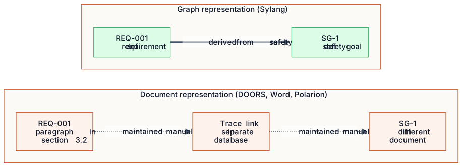
- Not navigable at the artifact level. To find every requirement that traces to a safety goal, you read the whole document or lean on a separate database.
- Not validatable. Your word processor won't flag a contradiction between a requirement and its safety goal.
- Not addressable. A reference is at best a fragile section number. At worst it's a textual cross-reference that a reviewer has to check by eye.
A graph flips each of these. It's navigable: every requirement is a node, every trace link is an edge, and which requirements trace to this safety goal? becomes a single query. It's validatable: each edge has a type (derivedfrom, implements, allocatedto, satisfies), and each type has rules about which node types it may connect.
A validator can check the whole graph against those rules in linear time. And it's addressable: every node has a stable identifier, and a reference from one node to another is a typed edge the validator can confirm exists.
Ontology: the graph's schema
A graph on its own isn't a model. It's a data structure. What turns it into a model is a schema that says which nodes and edges are legal. In database theory, that schema is the entity-relationship diagram: a meta-level spec of which entity types may exist and which relationships between them are allowed.
In knowledge representation, the same idea is called an ontology: the concepts in a domain and the relationships among them, written in a logic that supports mechanical reasoning. You'll also meet two neighbors. A taxonomy is a hierarchy (feature → sub-feature → leaf feature), and a schema is a set of allowed types and constraints. An ontology goes further than both by adding what the relationships mean.
The technical differences are real, but in this book I use ontology loosely. It means which artifact types exist in the MBSE model, which relationships between them are allowed, which constraints apply, and what you can infer from the graph's structure.
Compare that with SysML. The SysML 1.7 specification runs to about 1,200 pages and includes hundreds of element types. It allows so much variation that two SysML models built in different vendors' tools typically won't interoperate without manual reconciliation.
Sylang's small, explicit ontology is no accident. It's the design choice that makes the language a good fit for AI authors: if an agent can hold the whole ontology in view, it can author against it. Chapter 3 develops that choice in detail. Next, in 2.2, we'll look at how systems engineering arrived at SysML's 1,200-page ontology, and why that path makes the next step hard.
Exercises
You'll find the answer key for 2.1.1 in Appendix H.
2.2 Sixty years of MBSE: a working history
MBSE became a recognizable discipline in the 1990s, but its roots go back much further. They reach into the systems engineering that grew out of post-war defense and aerospace programs, and into the database, programming-language and software-engineering traditions that supplied its formal foundations. In this subchapter I trace that lineage just deeply enough to show you why today's MBSE tools look the way they do. That, in turn, explains why redesigning the modeling language is now both possible and worth doing.
Period 1: systems-engineering origins (1950s to 1970s)
Systems engineering took shape in the late 1950s and 1960s, around defense programs too complex for any single engineering discipline to manage. The Atlas intercontinental ballistic missile program (1955 to 1958), the Polaris fleet ballistic missile program (1957 to 1960) and the Apollo program (1961 to 1972) each developed distinctive practices. Those included explicit requirements traceability, configuration management, interface specifications between subsystems and, especially on Apollo, early forms of what would later be called systems analysis.
The first attempt to turn these practices into a teachable method was Hall's A Methodology for Systems Engineering (1962). It introduced the morphological matrix for organizing engineering decisions. The first widely adopted textbook was Chestnut's Systems Engineering Tools (1965).
On the standards side, MIL-STD-499 (1969) first codified systems-engineering practice for military procurement. It evolved through MIL-STD-499A (1974) and MIL-STD-499B (drafted in 1991, never finalized). It was later superseded by ANSI/EIA-632 (1998) and by today's ISO/IEC/IEEE 15288 (first published 2002, current edition 2023).
The V-model was first written down in DOD-STD-2167 (1985), and the German defense community had used it since the late 1970s. Bidirectional traceability is rooted in this period, but it only became mechanizable with the database tools of the 1980s. The WBS comes from the US Navy's PERT method for Polaris, and it survives today as the split into sprints, epics, stories and tasks.
Period 2: formalization era (1980s)
The 1980s brought formal methods into systems and software engineering. Three contributions from that decade are still visible in today's stack.
- Structured analysis methods from Yourdon, DeMarco and Constantine. The key texts are Structured Analysis and System Specification (DeMarco, 1979) and Modern Structured Analysis (Yourdon, 1989). Together they brought the data-flow diagram, the entity-relationship diagram and the state-transition diagram into everyday engineering. Much of what SysML and its successors now draw descends from these three diagram types.
- The formal specification tradition: Z (Spivey, 1989), VDM (Bjørner and Jones, 1982) and Larch (Guttag and Horning, 1993). It showed that engineering artifacts could be written in logics a machine can reason about. Mainstream adoption stayed limited, with Z and VDM used in a handful of high-assurance projects, notably the IBM CICS rewrite and the Praxis SHOLIS naval helicopter system. Its influence on MBSE is still substantial, especially the idea of artifacts that are validatable by construction.
- The relational-database tradition formalized the entity-relationship model (Chen, ACM Transactions on Database Systems, March 1976) and made schema design a discipline. By the late 1980s it had matured (Codd, The Relational Model for Database Management, 1990). It supplied much of the conceptual machinery that MBSE ontologies rely on today.
Period 3: object-oriented synthesis (1990s)
In the 1990s, the previous decade's threads came together as the object-oriented methods and notations that would dominate the next 20 years. Three methods competed in the early 1990s, each with its own notation: Booch's Object-Oriented Analysis and Design with Applications (1991), Rumbaugh's Object-Oriented Modeling and Design (1991) and Jacobson's Object-Oriented Software Engineering (1992). By 1994 the three were working together. By 1997 the Object Management Group (OMG) had adopted the Unified Modeling Language (UML) version 1.0.
Profiles turned out to be the most consequential addition. Through one of them, the SysML profile of UML, systems engineering got its first widely adopted graphical notation. The OMG and INCOSE developed SysML 1.0 together (OMG, September 2007), with sponsorship from the major aerospace and defense prime contractors.
SysML stretched UML's reach from software to whole systems: hardware, processes, facilities and human operators. It added five new diagram types (requirement, block definition, internal block, parametric and refined activity). It also limited UML's existing diagrams to the ones most relevant to systems engineering.
Period 4: the SysML moment (2007 onward)
Aerospace and defense adopted SysML 1.0 quickly, because sponsorship by the major primes guaranteed at least pilot deployments. Automotive and medical devices moved more slowly. There, ISO 26262 and IEC 62304 did not yet codify MBSE adoption.
MBSE tools that were production-ready by the early 2010s
| Tool | Origin | Current ownership | SysML support added |
|---|---|---|---|
| MagicDraw / Cameo | No Magic, 1998 | Dassault Systèmes (acq. 2018) | 2007 |
| Rhapsody | i-Logix, 1996 | IBM (acq. Telelogic 2006 → IBM 2008) | Native UML, SysML profile added later |
| Integrity Modeler | Artisan Studio | PTC (acq. 2013) | Early SysML adopter |
| Capella (open-source) | Thales, ≈2007 | Eclipse Foundation (PolarSys, 2014) | Arcadia method, not strict SysML |
How the standards moved in the same period
- ISO 26262 (Road vehicles: Functional safety): first published in 2011 in ten parts, with a major revision in 2018 (the current edition).
- IEC 61508 (Functional safety of electrical/electronic/programmable safety-related systems): current edition 2010.
- DO-178C (Software Considerations in Airborne Systems and Equipment Certification): replaced DO-178B in 2011. Its supplements are DO-330 (tool qualification), DO-331 (model-based development), DO-332 (object-oriented) and DO-333 (formal methods).
- IEC 62304 (Medical device software: Software life cycle processes): reached its current state with the 2015 amendment to the 2006 base.
- AIAG-VDA FMEA Handbook: in 2019, harmonized the American and German FMEA methods, which had previously diverged.
INCOSE's Systems Engineering Vision 2025 (published 2014) reflected that maturity. It named MBSE as the foundational transformation of systems engineering for the decade ahead. Vision 2035 (published 2021) reaffirmed the direction and added a prediction: artificial intelligence will become deeply integrated into systems engineering practice.
Period 5: the AI inflection (2022 onward)
The public release of GPT-3.5 (November 2022) and GPT-4 (March 2023) changed what the systems-engineering community expected AI to contribute. Within 12 months of GPT-4's release, every major MBSE tool vendor had announced an AI integration. IBM announced Watsonx for its Engineering Lifecycle Management platform (October 2023). Dassault announced its Generative Experience (June 2023), and Siemens its Industrial Copilot (April 2023, extended to Polarion in early 2024).
I released Sylang publicly in November 2024, with its tool family (Sylang Studio and the Hermes agent runtime), as my first attempt to make that architectural alternative available. This book follows about 18 months later. In it I argue, across the four anchor regulatory regimes, that the redesigned-language approach is economically viable. Treat that as a position for you to test, not a settled result.
Summary: where the lineage leaves us
The discipline got here by piling up decades of conceptual and tooling decisions, each one sensible in its time. That accumulation is what makes it workable for people: lots of established practice, a large community of trained engineers and broad regulatory acceptance. It's also exactly what makes the discipline resist the changes the AI inflection requires.
In 2.3 we'll look more closely at the regulatory standards. You'll see what they require, how those requirements meet MBSE practice, and what that means for the AI-authoring architecture the rest of this book builds.
Exercises
Your answers to 2.2.3 are your starting point for the adoption roadmap in Chapter 17.
The main gaps: the structured-development methods of Constantine and Yourdon; the architecture description language tradition of Allen and Garlan; the model-driven development movement of the early 2000s; Goal Structuring Notation for safety cases (Kelly, 1998); the systems-of-systems tradition associated with Maier (1998); and the digital-engineering practices of the US defense community since about 2018.
2.3 The standards landscape
If AI-authored MBSE artifacts have to pass regulatory audit, you need to know exactly what the regulators require. This subchapter gives you that. We'll survey the nine standards that govern safety-critical software and systems engineering across the book's four regulatory regimes (automotive, aerospace, medical devices and industrial automation). For each, we'll see what it demands of your engineering artifacts, then note where the standards agree and where they differ.
ISO 26262: road vehicles, functional safety
ISO 26262 is the main functional-safety standard for electrical and electronic systems in road vehicles. It was first published in 2011, and the current second edition dates from 2018. It adapts the general functional-safety framework of IEC 61508 to vehicles and adds three automotive-specific pieces.
- The item definition: the system boundary for the safety analysis.
- The hazard analysis and risk assessment (HARA): the method that determines the Automotive Safety Integrity Level, or ASIL.
- The safety case: the documented argument that the item is safe.
How the ASIL is determined
Each hazardous event gets three ratings: how bad the harm would be, how often the driving situation occurs, and how well the driver could avoid the harm. Together they set the ASIL.
| Parameter | Scale | Notes |
|---|---|---|
| Severity (S) | S0 (negligible) → S3 (life-threatening) | Impact of the hazardous event |
| Exposure (E) | E0 (incredibly rare) → E4 (high probability) | Operational situation frequency |
| Controllability (C) | C0 (controllable in general) → C3 (difficult/impossible to control) | Driver/operator's ability to avoid harm |
Combine S, E and C, and ISO 26262-3:2018 Table 4 gives you an ASIL of QM, A, B, C or D. ASIL-D carries the strictest process and verification requirements. QM (quality management) carries only the general engineering requirements of supporting standards, such as ISO 9001.
Of the four anchor regimes, an ASIL-D item under ISO 26262 calls for the most extensive set of work products. Chapter 12 walks you through the complete chain.
DO-178C: software in airborne systems
DO-178C is the main standard for certifying airborne software, published jointly by RTCA and EUROCAE in December 2011 (EUROCAE calls it ED-12C). ISO 26262 is a horizontal functional-safety standard, but DO-178C is process-prescriptive. It defines the life-cycle processes you must follow, the artifacts each process must produce, and the verification (review, analysis, test) each artifact needs. How much rigor applies depends on the software's Design Assurance Level (DAL).
| DAL | Failure condition | Example |
|---|---|---|
| Level A | Catastrophic (loss of aircraft) | Flight envelope protection, autoland |
| Level B | Hazardous failure | Navigation, flight management |
| Level C | Major failure | Cabin pressurization control |
| Level D | Minor failure | In-flight entertainment |
| Level E | No safety effect | Crew amenities |
IEC 62304: medical device software
IEC 62304 is the main standard for medical-device software life-cycle processes. It was first published in 2006 and amended in 2015. Like DO-178C, it's process-prescriptive. Unlike DO-178C, it ties closely into the wider medical-device risk-management framework of ISO 14971 (Medical devices: Application of risk management) and the quality-management framework of ISO 13485.
IEC 61508: functional safety, general
IEC 61508 is the parent standard that ISO 26262, IEC 62304 and several other domain-specific functional-safety standards derive from. Its current edition (2010) comes in seven parts. It defines safety integrity levels from SIL-1 to SIL-4, with SIL-4 the most stringent. It also defines the hazard and risk analysis method, the safety life-cycle activities, and the techniques and measures each SIL needs to achieve the required risk reduction.
Industrial automation typically invokes IEC 61508 directly. Domain-specific standards such as ISO 10218, ISO 13849 and IEC 61511 apply where relevant.
Supporting standards and process frameworks
Beyond those four primary functional-safety standards, you'll routinely meet several supporting standards in regulated-industry MBSE work.
- ASPICE (Automotive SPICE): a process-assessment framework, currently v4.0 (2023). ASPICE Level 3 is typical for ASIL-D supplier programs. Its demands for bidirectional traceability, configuration management and validation rigor line up closely with Sylang's artifact set.
- ARP 4754A (SAE Aerospace Recommended Practice, 2010): the aircraft-system development process that gives DO-178C its context. It defines the function allocation and failure conditions that drive the DAL of each piece of software within the system.
- ISO 21448 (SOTIF), Safety of the Intended Functionality (2019/2022): covers safety risks that arise from the intended functionality of automated systems. It's increasingly used alongside ISO 26262 for autonomous-driving and ADAS functions.
- AIAG-VDA FMEA Handbook (2019): the harmonized FMEA method used across the global automotive supplier base. It standardizes the seven-step process and the Action Priority scoring that has largely replaced the older RPN (risk priority number).
- ISO/IEC/IEEE 15288 (2023) and 12207 (2017): the general systems and software life-cycle standards that the domain-specific functional-safety standards operate under.
Where the regimes agree
The four primary standards differ a lot in their detailed requirements. Yet they agree on a small set of expectations for your engineering artifacts. Once you've seen this pattern under one standard, you'll spot it in the others.
- Hazard analysis is the entry point. Identify the safety-critical function, list the hazards and assess their severity. The terminology differs (ASIL, DAL, class, SIL), but the structural pattern is identical.
- Requirements derive from hazards, with explicit traceability from each requirement back to its hazard.
- Architecture allocates requirements to architectural elements (blocks, components, units). The allocation is documented and traceable in both directions.
- Verification closes the loop. Each requirement is verified with rigor scaled to its safety level, and each verification activity traces to the requirement it verifies.
- Configuration management preserves the chain. All artifacts sit under formal CM, with controlled change processes and documented baselines.
- A safety case integrates the evidence: a structured argument that the artifacts above are enough to conclude the system is safe enough for its intended use.
Where the regimes differ is in property values, in the rigor of the surrounding process, and in the form of the safety case. The artifact structure stays the same. Next, in 2.4, we'll place these artifacts on the V-model.
Exercises
There's no single right answer to 2.3.1. Defend each of your choices in two or three sentences.
For each regime in 2.3.2, identify which work product captures the equivalent of ISO 26262's .haz artifact.
I'm not aware of any free, legal source for the full texts as of 2025.
2.4 Where MBSE fits in the V-model
If you've worked in regulated-industry engineering, you've seen the V-model diagram. Because it's everywhere, people often understand it less precisely than they think. In this subchapter I'll restore that precision and show you where MBSE artifacts live in the V. I'll keep it brief, since the V-model isn't new, but placing the Sylang artifacts in it shows you how the artifact types fit into an end-to-end process.
Where the V came from
The V-model first appeared in its modern form in DOD-STD-2167 (Defense System Software Development, 1985) and in the German V-Modell 92 of the same period. V-Modell 92 was later superseded by V-Modell XT (current version 2.3, 2020). The earliest known drawing of the V is in the West German V-Modell documentation of 1986. The core idea, that verification activities mirror development activities, had been stated independently in several places before that.
MBSE lives on the left arm of the V
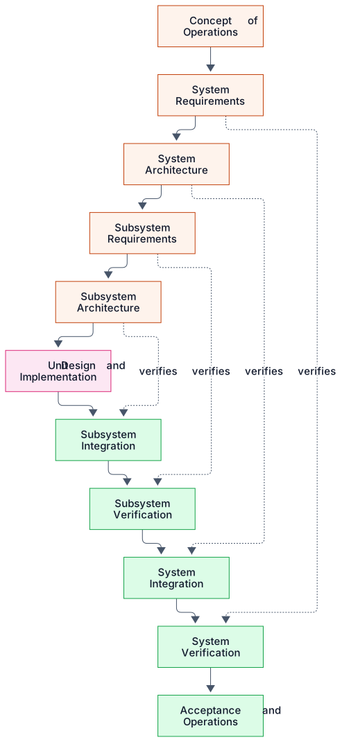
Most MBSE artifacts live on the left arm of the V. That's where you capture the decomposition, from the concept of operations all the way down to implementation. The table below maps each level to Sylang file types. If the extensions are new to you, don't worry: Chapter 3 introduces every one.
Where each Sylang artifact type sits
| V-model level | Sylang artifact types | ISO 26262 part |
|---|---|---|
| Concept of operations | .ple, .fml | Part 3 §5 |
| System requirements | .fun, .req (system level) | Part 3 §6, §7 |
| System architecture | .blk, .ifc, .smd, .ucd, .seq | Part 4 §7 |
| Subsystem requirements | .req (subsystem), .itm, .haz, .sgl | Part 4 §6, Part 3 §6-§8 |
| Subsystem architecture | .blk, .ifc, .smd (subsystem), .sam | Part 4 §7, §9 |
| Unit design and implementation | .blk (component), .flr, .fta | Part 6 §7-§9; Part 5 §9 |
| Verification (all levels) | .tst (via level enum) | Part 6 §9-§11, Part 4 §8 |
The mapping is approximate. Some Sylang artifact types span several levels: .blk is used at system, subsystem and component level, told apart by its level property. And some levels are served by several artifact types working together.
What lives on the right arm
The right arm covers verification and integration. In Sylang, the .tst (test set) file type does most of the work there. Supporting artifacts include .flr (FMEA, which captures failure analyses relevant to verification) and the .spec and .dash files, which show verification status to reviewers. The satisfies relationship (testcase → requirement) is the main edge connecting the right arm to the left.
The conventional V-model is sometimes criticized for understating verification planning during the development arm. Some practitioners treat verification as something done after development, not alongside it.
This built-in verification planning is what makes the reactive documentation approach of Chapter 16 possible. The verification status of every requirement becomes a query result you can regenerate at any time. So can the auditor.
The conventional V keeps verification status in a separate test-management system (TestComplete, Polarion Test Management, IBM ETM), connected to the requirements through trace links maintained by hand. Sylang folds those test-management relationships into the same artifact graph. That removes the separate system and the cost of maintaining it.
Summary: the V as scaffolding
The V-model works best as scaffolding for organizing your artifacts, not as a rulebook for when activities happen. The artifact relationships matter: every left-arm artifact needs a paired right-arm artifact, with a trace both forward and backward. But real programs are rarely as strictly waterfall as a naive reading suggests. Most modern regulated-industry programs run some form of iterative V or scaled agile, where V-shaped slices of work overlap.
In 2.5 we close the conceptual foundations and turn to the technical critique that Chapter 1 sketched. Why do today's MBSE tools, built on the foundations this chapter has covered, fail once AI becomes the primary author?
Exercises
When you finish 2.4.3, you'll have walked the entire left arm of the V starting from the verification arm, five edges deep.
Each variant addresses something the basic V handles awkwardly. The Sylang artifact set is compatible with all of them, because choosing a method is a separate decision from choosing a modeling language.
2.5 Why the present generation of MBSE tools failed AI
Subchapters 2.1 to 2.4 gave you the context in which today's MBSE tools were built and now operate. Here I close Chapter 2 by drawing the conclusion. The architectural commitments the major vendors made between 2005 and 2012 were defensible, even excellent, in their original context. They are also the reason current AI integrations fail in the ways Chapter 1 described.
Part 1: how SysML accidentally resists programmatic authorship
Judged purely as a graphical notation for systems engineering, the SysML 1.0 specification (OMG, 2007) is a substantial achievement. Its five new diagram types (requirement, block definition, internal block, parametric, refined activity) cover the core decomposition and behavior-specification needs of systems engineering with notational economy. Its metamodel, the abstract syntax that defines what a SysML model is apart from any drawing of it, is internally consistent and rigorously specified.
The trouble starts when software, rather than a person at a graphical editor, has to write the model. That's what I mean by programmatic authorship, and it's exactly what an AI agent does.
The two decisions
Decision 1: SysML as a UML profile
SysML was specified as a profile of UML 2, not as a standalone language.
That was politically necessary at the time. It gave access to the existing UML tool ecosystem and reduced vendor engineering effort.
Consequence: every SysML model is mechanically a UML model with stereotype annotations. The full UML 2 metamodel (roughly 250 metaclasses and several thousand attributes) is present whether or not the engineer touches any UML feature that SysML doesn't expose. That complexity is hidden from a human user, but not from an AI agent.
Decision 2: XMI for interchange
SysML was specified to exchange models through XMI (XML Metadata Interchange).
On the surface it's plain text, so it looks easy to write with code.
Three properties defeat that expectation: opaque internal identifiers (UUIDs); diagram layout stored separately and partly vendor-specific; and large reserved-attribute namespaces that vendors fill in their own ways. As a result, an XMI file from one tool typically won't load in another without manual reconciliation.
The SysML 2.0 specification (expected 2026 or 2027) addresses both decisions substantially through a new textual notation. Whether it will be adopted fast enough to displace the installed base is uncertain.
Part 2: the ecosystem around the tools
Beyond the notation, the dominant MBSE tools made a set of ecosystem decisions that constrain AI authorship further. They cluster around four properties of the tools as deployed in industry.
- Licensing model. Licenses are per seat or floating. As a rough illustration, enterprise editions can run somewhere around $5,000 to $15,000 per seat per year. The model assumes licensed users are human engineers, and how to license an AI agent running perhaps an order of magnitude more sessions than a person is unresolved. A serious AI-authoring deployment needs either many more seats or a special arrangement with the vendor.
- Deployment topology. The tools are desktop applications (Rhapsody, Cameo) or on-premises web apps (Polarion, DOORS Next). Desktop apps expose limited remote-control APIs, and web apps expose REST APIs whose coverage and throughput vary widely. Either way, the agent must work inside the tool's process or hit its API at a throughput it wasn't designed for, and both make operations fragile.
- Concurrent-author semantics. These range from full pessimistic locking (early Rhapsody), through optimistic check-out and check-in (DOORS Next), to concurrent editing based on operational transformation (recent Cameo Teamwork Cloud). None was designed for dozens of AI agents proposing changes at the same time, so you should expect conflict resolution to struggle under that load.
- Change-management integration. Integration packs for Rational Team Concert, Polarion ALM, Teamwork Cloud and Azure DevOps are only loosely coupled to the modeling tools, and they don't capture the agent's reasoning. The audit trail they support suits human authorship. It isn't what an auditor needs to evaluate AI-authored changes.
Part 3: the assumption stack
That assumption breaks down into six more specific ones, and each is now in question. Treat the figures in the table as rough illustrations of scale, not measurements.
| Assumption | Under human authorship | Under AI authorship |
|---|---|---|
| Pace | ~1 modification/minute; validator latency invisible | Tens of operations/second; 2 to 10 s latency is the bottleneck |
| Cardinality | Single author at a time, check-in/check-out conventions | Many concurrent agents; conflict semantics undefined |
| Judgment | Human applies judgment to ambiguous errors | Agent cannot resolve ambiguity without external grounding |
| Reasoning capture | Captured informally (comments, minutes, conversation) | Reasoning too voluminous and structured for informal media |
| Tool fluency | User has years of accumulated knowledge of tool quirks | Agent consumes documentation as primary input, so the tool must be self-documenting |
| Format opacity | User does not directly inspect serialization | Agent must inspect it directly: serialization is the only form it can read |
Part 4: the path forward
If today's MBSE tools were built for an assumption stack that no longer holds, the way forward can take one of two shapes. A tool built for a human at a keyboard won't become an AI-native tool by accident.
Path 1: retrofit
Add programmatic-authoring APIs to existing tools.
Redesign validators to produce machine-readable errors.
Integrate change management into the model.
Standardize the serialization format.
Path 2: redesign
Design a new modeling language and surrounding tool stack for AI authorship, from the foundation up.
Explicit intention: coexist with the present generation at the regulatory boundary.
Migration from the present stack is gradual and driven by customers.
I defend that position through the rest of the book and illustrate it with the four anchor projects. The next chapters give you the technical detail to evaluate it for yourself.
Exercises
To finish 2.5.1, list three concrete obstacles that agent would hit.
As a rough rule of thumb for 2.5.2, a total below 18 suggests you're already feeling the failure modes of Chapter 1.
Key takeaways
You’ve got this chapter if you remember:
- In MBSE, a model is a descriptive model: artifacts plus the typed relationships among them, which makes it a graph, not a document.
- A graph is navigable, validatable and addressable, and those three properties are exactly what AI agents can exploit.
- ISO 26262, DO-178C, IEC 62304 and IEC 61508 use different terms but share one pattern: hazards drive requirements, architecture allocates them, verification closes the loop, and a safety case integrates the evidence.
- MBSE artifacts mostly live on the V-model's left arm, and verification should be planned as each requirement is written, not at the end.
- Today's MBSE tools assume a human author at a graphical editor; once AI does the authoring, that assumption fails, leaving a choice between retrofit and redesign.
Check yourself
Answer in your head first, then reveal.
1Which of the four senses of model does MBSE mainly mean?
The descriptive sense: a structured representation of how a system decomposes into parts and how those parts relate.
2What three properties does a graph have that a document lacks?
It's navigable at the artifact level, validatable against rules for each edge type, and addressable through stable identifiers.
3Which three ratings determine an ASIL under ISO 26262?
Severity (S), Exposure (E) and Controllability (C). ISO 26262-3:2018 Table 4 maps their combination to QM or ASIL A, B, C or D.
4Which two SysML design decisions became obstacles for AI authorship?
Specifying SysML as a profile of UML 2, which brings the full UML metamodel along, and using XMI for interchange, with its opaque identifiers and vendor-specific content.